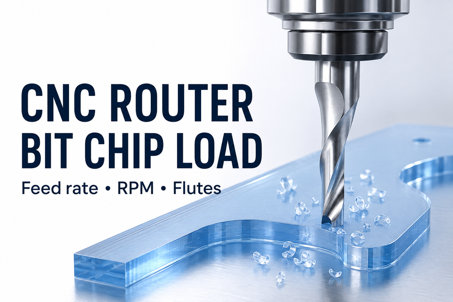
CNC router bit chip load connects feed rate, spindle RPM, and flute count. Calculate nominal feed per tooth by dividing feed rate by RPM multiplied by the number of cutting edges. Then compare the result with the tool maker’s data for the exact cutter, material, and operation. A calculation helps organize a setup; it does not establish a safe cutting range by itself.
1. Check the CNC router bit chip load formula
Chip load = feed rate / (RPM x cutting edges). Rearranging gives feed rate = chip load x RPM x cutting edges. Use mm/min with mm/tooth, or inches/min with inches/tooth. RPM means revolutions per minute. Count the effective cutting edges, not the number of grooves you assume a tool has.
This relationship is also explained in Vision’s router feed-rate calculation guide. Its example concerns a particular tool and machine, so do not copy those operating values to a different cutter.
2. Separate an arithmetic example from a cutting recommendation
Suppose a hypothetical one-edge tool moves at 1,800 mm/min while rotating at 18,000 RPM. The calculation is 1,800 / (18,000 x 1) = 0.10 mm/tooth. At the same feed and RPM, two cutting edges give 0.05 mm/tooth. These numbers demonstrate the equation only; they are not settings recommended for a JEEFOO product.
Holding the hypothetical 0.10 mm/tooth constant with two edges would require 3,600 mm/min at 18,000 RPM. This CNC router bit chip load example shows why changing flute count requires reviewing the whole setup. If your controller uses mm/second, 1,800 mm/min equals 30 mm/second. Label the units beside every number before entering a program.
3. Match the calculation to the actual job
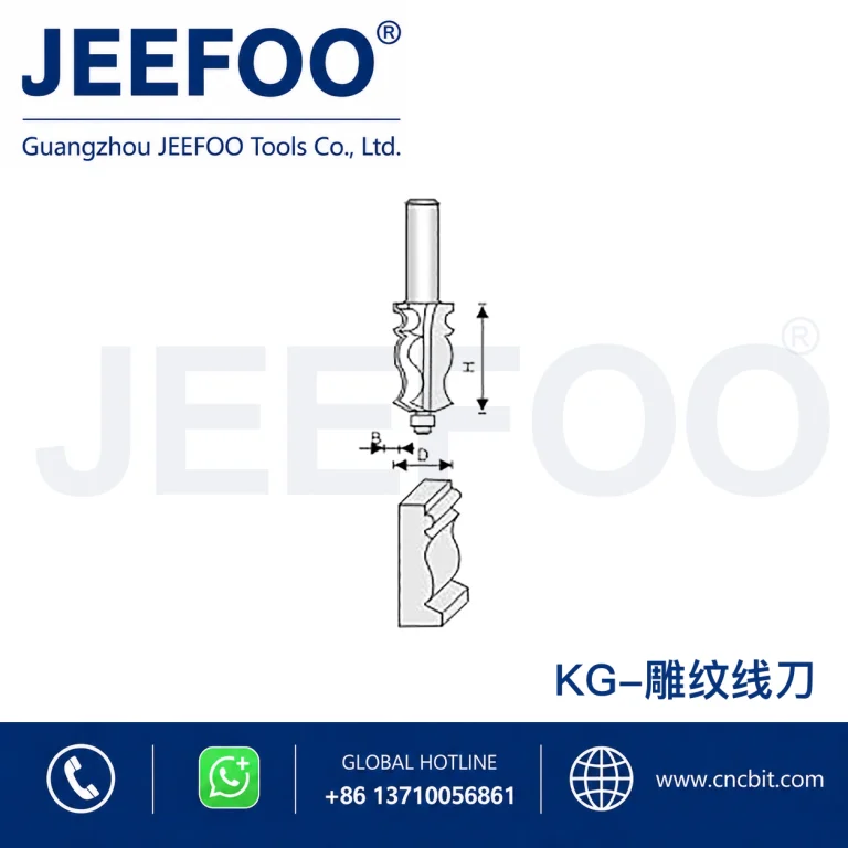
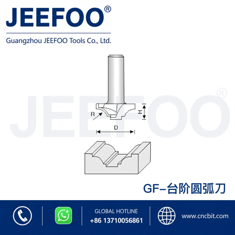
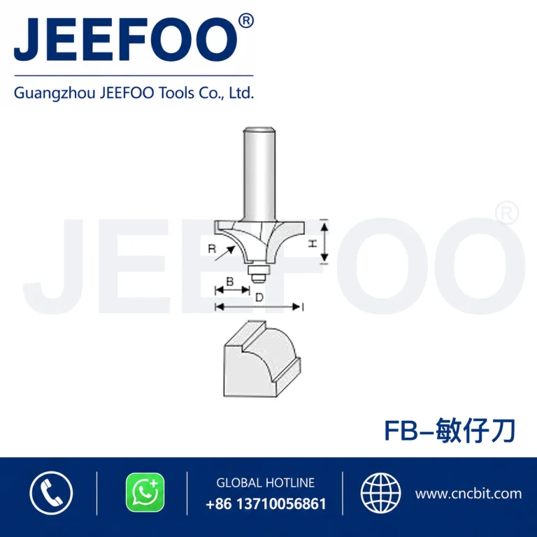
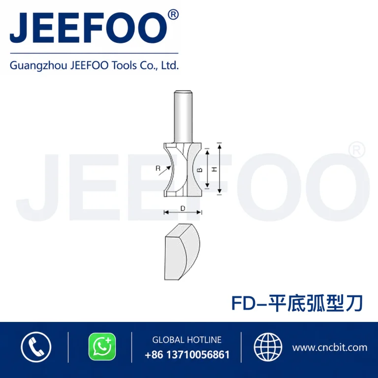
Record the tool code, cutting diameter, shank diameter, flute count, material grade, sheet thickness, and intended operation. Ask for cutting data that matches those details, including the permitted depth and width of cut. For a broader introduction to geometry and dimensions, see our CNC router bit selection guide.
Keep a separate entry for spindle RPM, programmed feed, and controller feed override. A worksheet is more useful when another operator can reconstruct the trial without guessing which number was changed. Save the tool supplier’s data revision or date with the job record.
4. Check chip evacuation and workholding
For plastic routing, heat and chip removal deserve particular attention. LMT Onsrud identifies inappropriate chip load, limited chip clearance, unsuitable geometry, poor hold-down, and tool-holder condition as possible contributors to welding or poor finish. Its plastic-routing troubleshooting guide explains why changing feed alone may leave the underlying problem unresolved.
Use the machine manufacturer’s procedures for securing the part, installing the tool, and managing chips. Stop the machine before inspecting the edge or clearing material. Treat a deteriorating finish as a reason to investigate the setup, rather than automatically increasing spindle speed.
5. Keep a repeatable test-cut record
Start from confirmed supplier guidance and run a controlled trial on suitable sample material. Record the initial settings, the feature tested, and the observed result. Change one agreed variable at a time within the equipment and tooling limits. Photograph the sample and identify it with a trial number, so the written notes and physical part stay connected.
Our suggested CNC router bit chip load record has five fields: setup reference, calculated chip load, test change, edge-quality observation, and next action. Include an acceptance requirement from the drawing or customer brief. A useful result is a documented process that meets the job’s needs, not simply the largest feed number the controller accepts.
CNC router bit chip load FAQ
Is chip load the same as cutting depth?
No. Nominal chip load is feed per cutting edge; cutting depth describes tool engagement into the material. Record both when requesting setup advice.
Does doubling RPM double chip load?
No. With feed and edge count unchanged, doubling RPM halves the calculated feed per tooth. Recalculate whenever one of the three inputs changes.
Can one chip-load value cover every material?
No universal value is established by this formula. Confirm the exact cutter and material combination, then validate the setup with the supplier’s guidance and a test cut.