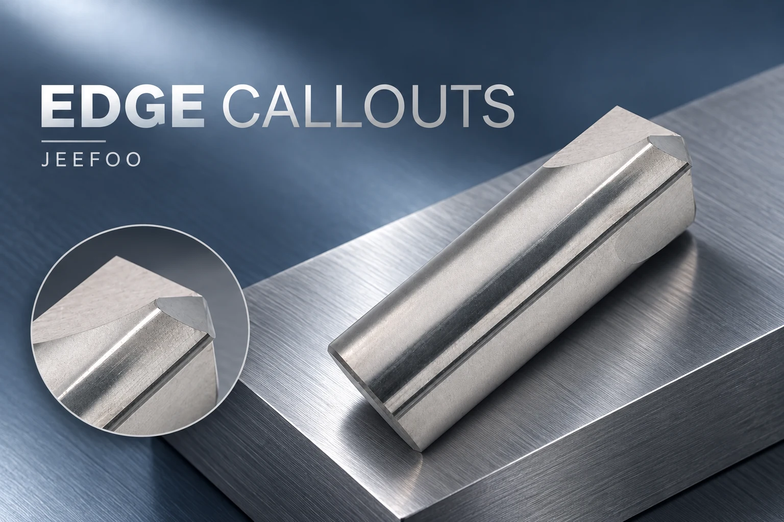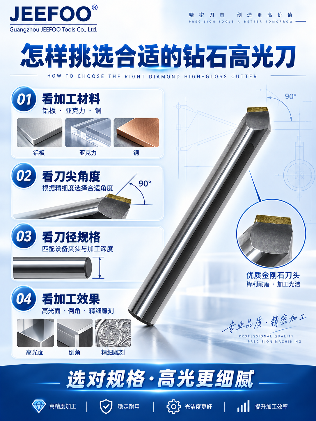
An aluminum chamfer cutter should be selected against a defined edge requirement, rather than the instruction to “take the sharp edge off.” JEEFOO’s LJ series covers aluminum chamfering and edge preparation. Before generating the toolpath, identify whether the drawing asks for a controlled chamfer, a general edge break or a feature that affects assembly.
1. Define the Aluminum Chamfer Cutter Edge Callout
A width shown on the top face, a length measured down the side and the width of the sloping face are different quantities. Make sure the programmer and inspector use the same reference. The angle also needs an identified reference face; a cutter’s included angle should not be casually substituted for the finished-face angle.
If the drawing is ambiguous, resolve it with the drawing owner before machining. A photograph of a pleasing edge cannot establish the dimension or tolerance of a functional feature. Preserve the agreed interpretation with the job documentation.
Identify the edges that must remain unchanged
A continuous outer contour may include sealing lands, seating surfaces, threaded openings or features close to the edge. Decide which segments are included in the chamfer operation and which are excluded. Applying the same toolpath around every visible boundary can remove material from a functional area.
Where a chamfer meets another machined feature, review the intersection in the model. The resulting local shape matters more than the appearance of a simple straight-edge sample. Keep exclusions clearly named so a later model update does not accidentally add them back.
Translate the requirement into a verified tool definition
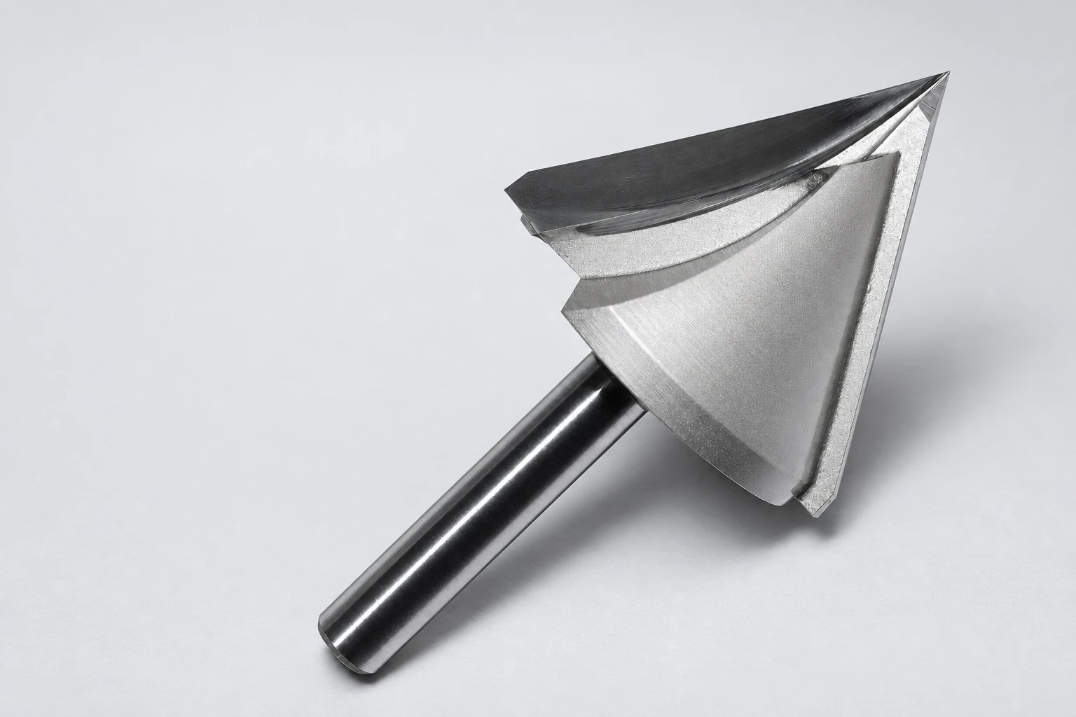
Confirm the actual LJ cutter geometry from the supplied drawing and match it to the CAM definition. Product-code numbers should not be treated as a complete dimensional specification. The working part of the cutting edge must suit the requested feature and the available approach.
Select an inspection method that can check the specified dimension on the finished component. Record which face or edge provides the reference. This makes the result reproducible when the job is repeated or transferred to another operator.
A clear edge callout connects design, programming and inspection. With that requirement settled, the aluminum chamfer cutter can be applied to a specific, measurable task.
Aluminum Chamfer Cutter: Quick Answers
Are included angle and finished-face angle interchangeable?
No. Identify the angle convention and reference face on both the part drawing and cutter drawing. Harvey Performance’s chamfer cutter guide highlights this distinction and the need to consider tip geometry and interference. Confirm the actual LJ-series geometry separately.
Does a general edge break define a controlled chamfer?
No. Resolve the required size, angle, tolerance and inspection reference with the drawing owner. A pleasing sample or photograph does not establish the limits for a functional edge.
Should every visible edge be chamfered?
No. Identify exclusions such as sealing lands, seating faces, threaded openings and nearby features. Review intersections in the model and preserve the approved exclusions with the job.
What should be sent with a tooling enquiry?
Provide the alloy, edge callout, reference faces, tolerance, approach clearance and inspection method in your JEEFOO tooling enquiry. Match the supplied cutter drawing to CAM rather than interpreting product-code numbers as a full specification.