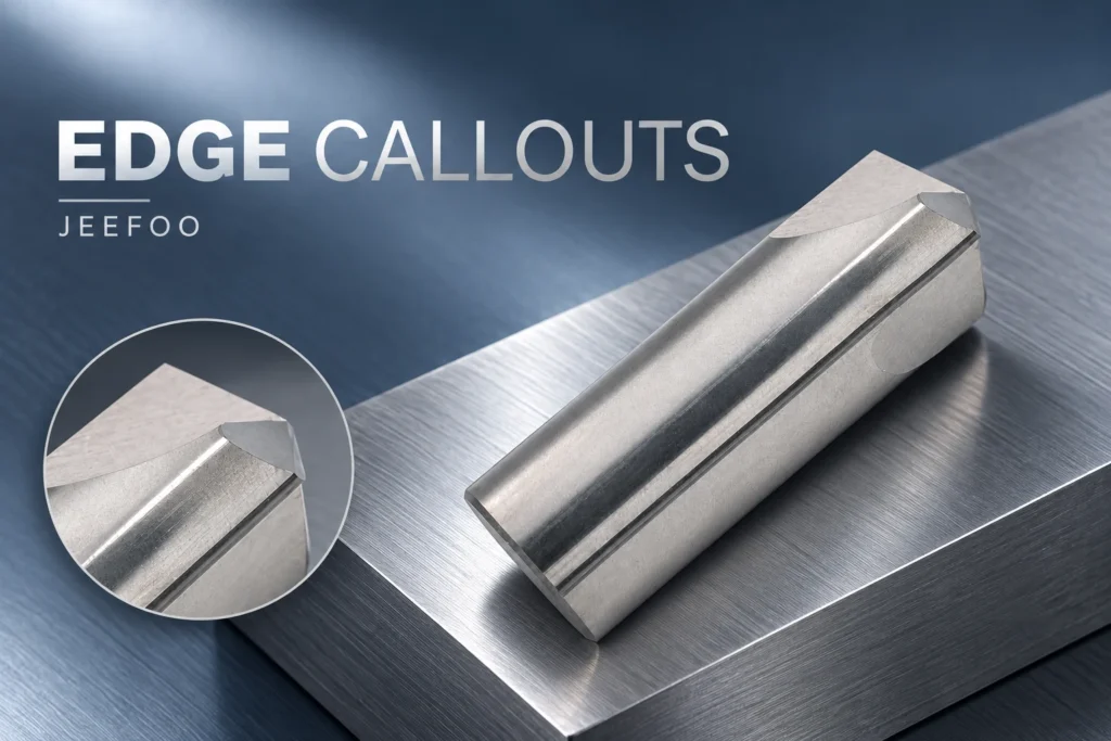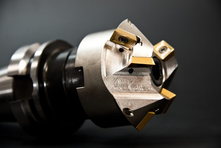
An aluminum radius profile cutter must match the required cross-section and its orientation on the part. JEEFOO lists the GZ12 16xR7 model as an Inner R cutter. That product name alone does not establish which finished corner it will produce in a particular setup. Compare the actual tool profile with the component section before programming.
Aluminum Radius Profile Cutter: Confirm the Tool Contour
A curved cutting edge and a curved surface on the workpiece are related through their contact and motion. Looking at a photograph of the tool without considering its orientation can lead to the wrong conclusion about the resulting feature.
Start with a section through the component at the intended cut. Mark the faces that must remain, the desired transition and the side from which the cutter approaches. Then compare that section with the verified tool drawing. Do not assume that a family name guarantees an internal wall-to-floor fillet or an external edge roundover.
Check the complete transition, not an isolated arc
A nominal radius describes only one part of the requirement. The arc must also meet the adjacent faces at the specified locations. A profile that looks broadly similar can still leave an unwanted step, land or mismatch at one end.
Use the model to review both ends of the transition and nearby features. Ask for clarification if the drawing leaves the intended tangency or remaining land undefined. This is a design question that should be resolved before selecting a convenient cutter path.
Verify orientation in the CAM model
Create the tool from confirmed profile data and check its position against the component section. Include the complete shaped head rather than reducing it to a generic cylinder or a nominal radius symbol.
Review the simulated material removal from more than one section along the feature, especially where the surrounding part changes shape. Keep the approved tool drawing and model revision together, so a future substitution can be compared against the same requirement.
For a radius profile cutter, the useful question is whether the actual cutting contour produces the required section in the planned orientation. A matching R label is a starting reference, not proof of that match.
Aluminum Radius Profile Cutter: Quick Answers
Does an R7 label confirm the finished corner shape?
No. A nominal radius does not identify the complete profile, approach direction, or tangent locations. Compare the actual tool drawing with the component cross-section, including the faces and lands that must remain.
Is a corner-radius end mill the same as a form cutter?
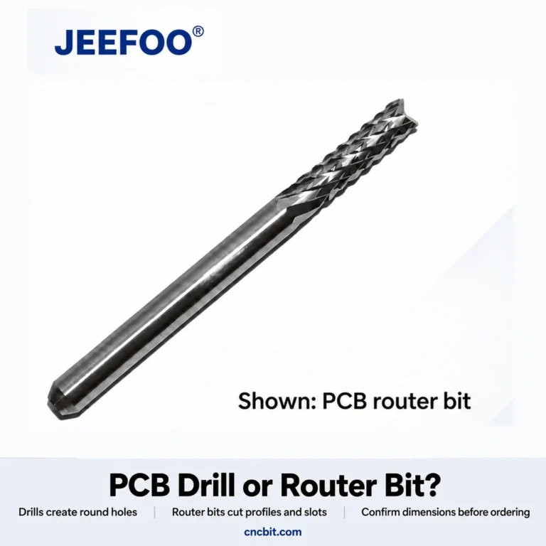
No. A radius at the corner of an end mill and a shaped cutting edge intended to generate a profile describe different geometries. Select from the verified contour and intended operation rather than a similar product name.
What should be checked on the trial part?
Inspect the radius, its junctions with adjacent faces, remaining lands, and nearby dimensions against the released drawing. Use a suitable profile measurement method; visual similarity alone does not establish conformity. Record the tool reference, orientation, program revision, and inspection result together.
Harvey Performance’s corner-rounding guide illustrates why pilot geometry, access direction, and flared or unflared transitions affect tool selection. These are general selection considerations, not specifications for the JEEFOO GZ12. For another edge geometry, see our aluminum chamfer cutter guide.