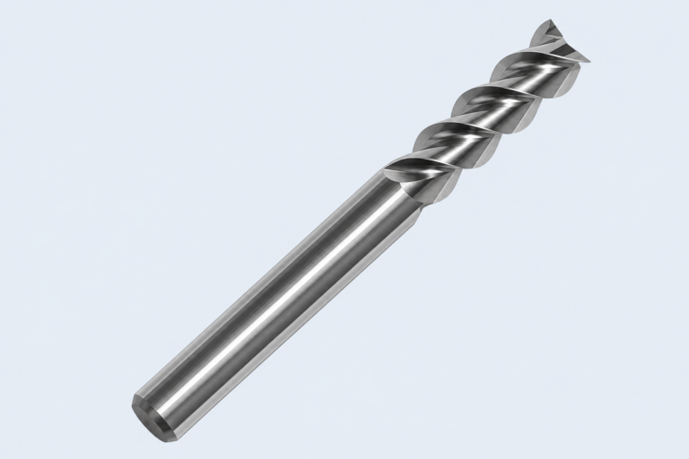
The floor of a circular O-ring groove in a steel cover measures to depth. Before signing the machining report, check what else the drawing controls. JEEFOO lists its MA square end mill for slotting and side milling in compatible metals. A depth measurement records where the cutter bottom finished. It says little about where the two sidewalls of an MA-cut face groove ended up.
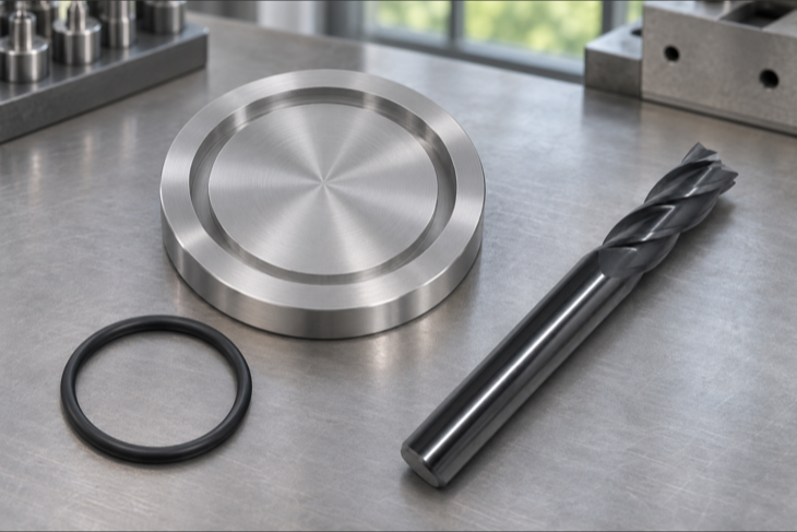
First draw the cover in its assembled position. Suppose its flat face seats directly on the mating face, with the same unstretched ring in either of two proposed grooves. Apple Rubber calls the compression between the top and bottom of the ring axial squeeze. In this example the distance from the groove floor to the mating face stays the same in both drawings. So does the nominal squeeze.
Now trace the radial widths of the MA-cut face groove. Picture rectangular sections with equal depth and the same mean circumference. If one groove is 8 mm wide and the other 10 mm, the wider one has 25% more volume. Parker defines gland fill as the ring volume divided by the available gland volume. The same ring therefore occupies a smaller fraction of the wider groove. The squeeze calculation still uses the same closed height.
On the finished cover, record the inner and outer wall diameters of the MA-cut face groove alongside the depth. For concentric walls, half the difference between those diameters gives the radial width. Compare each diameter with the drawing as well. A groove of the right width can still be in the wrong radial position. Mark both wall locations in the inspection sketch.