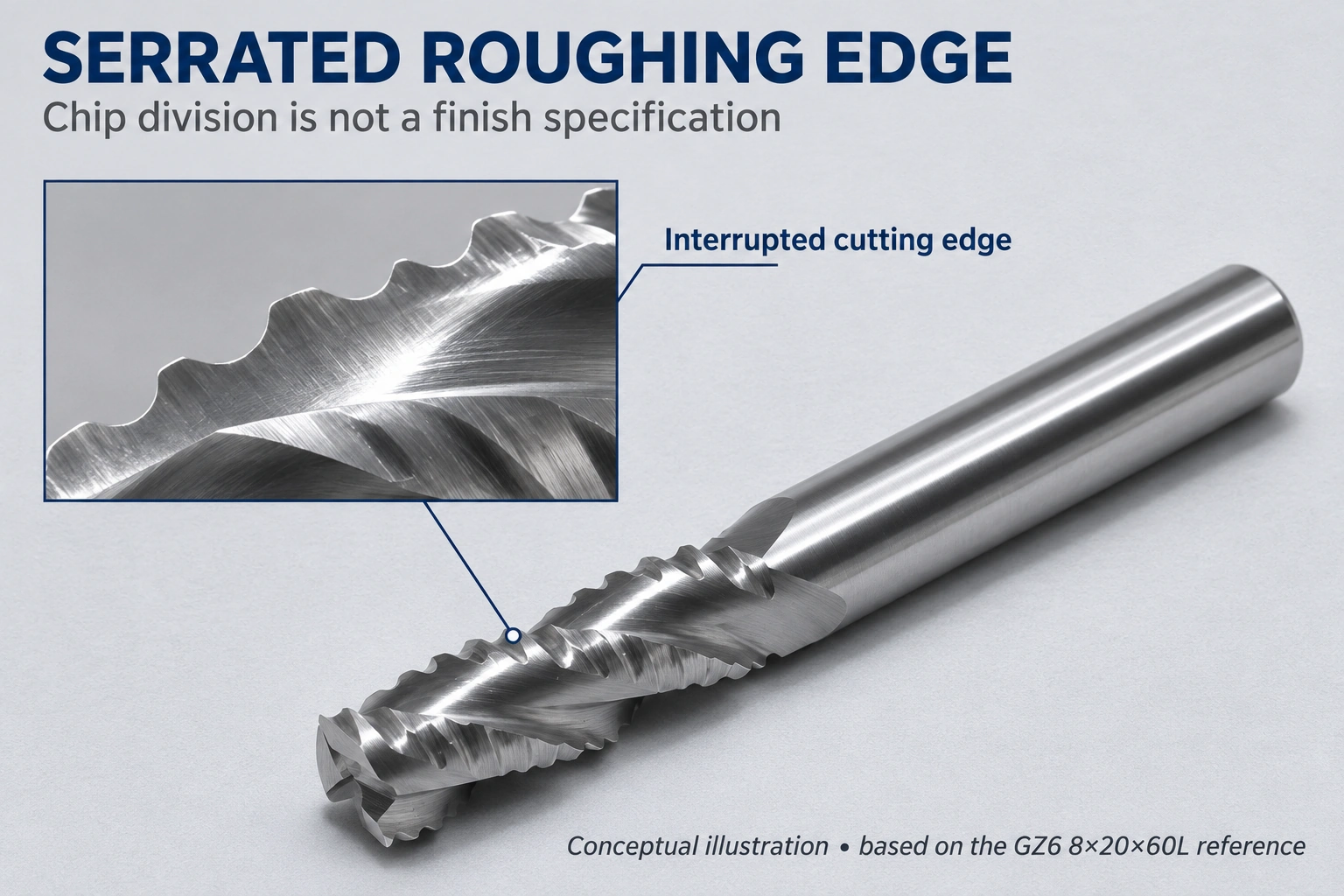
Roughing end mill serrations interrupt the cutting edges and divide the chip. That changes how material leaves the cut; it does not, by itself, define the final wall finish or dimensional tolerance. For a component that requires a controlled finished surface, the roughing operation and the finishing operation need separate objectives.
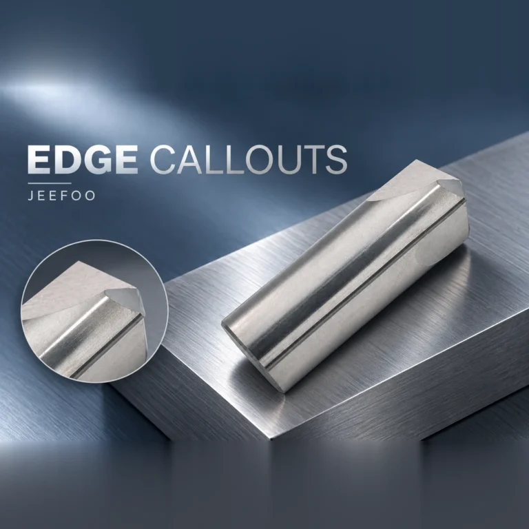
The JEEFOO 8×20×60L roughing end mill provides a concrete example. Its product page identifies an 8 mm cutting diameter, 20 mm cutting length and 60 mm overall length, with serrated cutting geometry intended for stock removal. Those dimensions describe the cutter, not a universal cutting recipe.
The current listing contains conflicting application information: its text refers to metals, while its specification image lists acrylic, PVC and plastic board. This article therefore uses the GZ6 reference only to discuss visible serrated geometry, not to confirm material suitability or cutting conditions.
What roughing end mill serrations change
A continuous edge engages material over its active length. A serrated edge introduces local interruptions, so the chip is divided rather than remaining one uninterrupted strip. Harvey Performance’s explanation of chipbreaker tooling describes how interruptions in cutting edges can break chips into smaller pieces. “Rougher” therefore identifies an edge arrangement and an intended role, not simply an end mill run at a higher feed.
Recognizing roughing end mill serrations is useful when planning a pocket. The CAM path determines where the cutter moves. The edge geometry determines how the material encountered by that path is removed. A change to one does not erase the constraints of the other: chip escape, tool access and the rigidity of the machine remain part of the same operation.
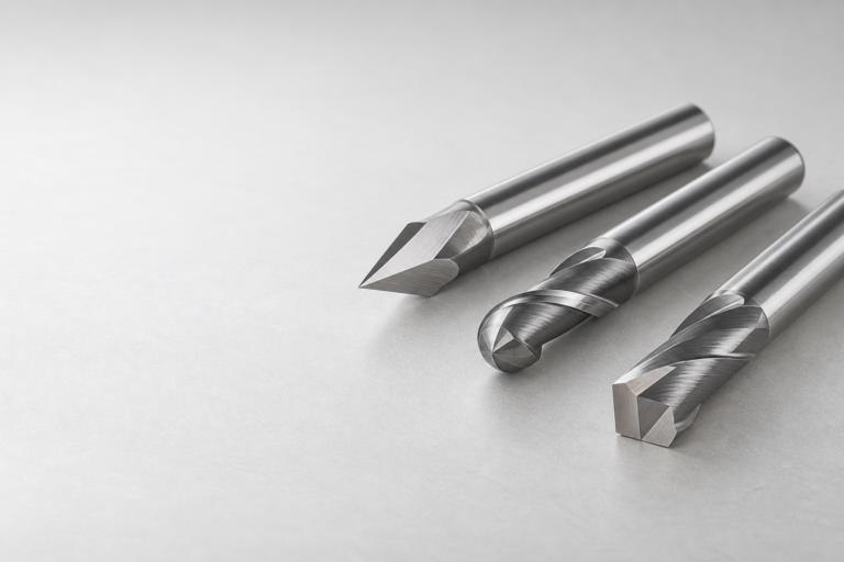
A serrated rougher, a chipbreaker and a worn cutting edge should not be treated as equivalent just because a photograph shows interruptions. Identification must come from the cutter’s documented geometry rather than from a blurred image alone.
Why finishing remains a separate question
A short chip is not evidence of a finished wall. Surface requirements belong to the drawing and the downstream function of the part. A sealing face, a sliding fit and a hidden clearance pocket may have different requirements even when they begin with the same roughing operation.
The local JEEFOO page explicitly describes this tool as a roughing cutter used before a final pass. The practical implication is to retain material for the chosen finishing strategy instead of assuming that a visually regular roughing pattern is acceptable. No fixed allowance is proposed here: the appropriate amount depends on the geometry, stock condition, finishing cutter and process.
There are also different kinds of interrupted-edge tools. The same Harvey explanation discusses offset interruptions and chip evacuation. Its examples are manufacturer-specific. Their surface results or operating parameters must not be transferred to the JEEFOO cutter merely because both tools have notches.
Two decisions that should not be collapsed
The first decision is whether a chip-dividing roughing edge suits the material and the available machine setup. The second is how the final surface and dimensions will be produced. Combining these into the single question “Will this cutter cut faster?” leaves the finishing requirement undefined.
For a tooling discussion, describe the material and the feature being roughed, then explain which faces must be finished and how the finishing tool reaches them. The useful comparison is a complete roughing-and-finishing route, not an isolated promise about removal rate.
Conclusion
Roughing end mill serrations explain a chip-formation mechanism. They do not certify a particular surface, replace a finishing plan or justify borrowed feeds and speeds. Use the actual cutter specification to define the roughing role, and use the component requirements to define what must happen afterwards.